The proposed methods have been tested on a data set acquired at
RTS, Hannover. Fig. ![]() shows a single 3D scan with
semantic labeling. Fig.
shows a single 3D scan with
semantic labeling. Fig. ![]() presents the final map,
consisting of five 3D scans, each containing 43440 points. Table
presents the final map,
consisting of five 3D scans, each containing 43440 points. Table
![]() shows the computing time for matching of two 3D
scans. Using semantically labeled points results in a speedup of
up to 30% with no loss of quality.
shows the computing time for matching of two 3D
scans. Using semantically labeled points results in a speedup of
up to 30% with no loss of quality.
![\includegraphics[width=60mm]{full_map}](img76.png)
![\includegraphics[width=60mm]{full_map_top_view}](img77.png)
|
| used points | search method | computing time | number of iterations |
| all points | 17151.00 ms | 49 | |
| reduced points | 2811.21 ms | 38 | |
| all points | forest of |
12151.50 ms | 39 |
| reduced points | forest of |
2417.19 ms | 35 |
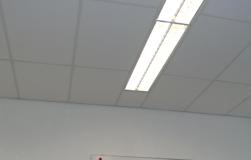
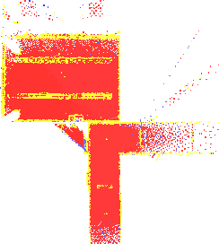
Fig. ![]() shows a detailed view of the
ceiling. 3D points belonging to the lamp at the ceiling are also
colored yellow. The correct match will be in no way affected by
this fact. In fact, the semantic meaning is that data points of
the lamp will be matched correctly with their correspondents.
shows a detailed view of the
ceiling. 3D points belonging to the lamp at the ceiling are also
colored yellow. The correct match will be in no way affected by
this fact. In fact, the semantic meaning is that data points of
the lamp will be matched correctly with their correspondents.
|
Contrary to previous works, every single 3D scan is a full
360![]() scan. They are acquired in a stop-scan-go fashion to
ensure consistency within the single 3D scans. In RoboCup Rescue
the operator drives the robot and acquires 3D scans. In the 2004
competition we encountered that the overlap between two
consecutive scans was sometimes too low, so that the operator had
to intervene in the matching process. The new scanner will reduce
this problem, since it provides backward
vision. Fig.
scan. They are acquired in a stop-scan-go fashion to
ensure consistency within the single 3D scans. In RoboCup Rescue
the operator drives the robot and acquires 3D scans. In the 2004
competition we encountered that the overlap between two
consecutive scans was sometimes too low, so that the operator had
to intervene in the matching process. The new scanner will reduce
this problem, since it provides backward
vision. Fig. ![]() shows the analogous map of
Fig.
shows the analogous map of
Fig. ![]() without backwards vision, i.e., the algorithm
uses only points that lie in front of the robot. The 3D scans can
no longer be matched precisely, the map shows inaccuracies for
example at the lab door. In fact, doors and passages are a
general problem of mapping algorithms, due to the small
overlap. Fig.
without backwards vision, i.e., the algorithm
uses only points that lie in front of the robot. The 3D scans can
no longer be matched precisely, the map shows inaccuracies for
example at the lab door. In fact, doors and passages are a
general problem of mapping algorithms, due to the small
overlap. Fig. ![]() shows the final map of an
additional experiment with 9 3D scans and 434400 data points.
shows the final map of an
additional experiment with 9 3D scans and 434400 data points.
This paper presented a robotic 3D mapping system consisting
of a robot platform and a 3D laser scanner. The laser scanner
provides a 360![]() vision; the scan matching software,
based on the well-known ICP algorithm, uses semantic labels to
establish correspondences. Both approaches improve previous work,
e.g., [9,10], in terms of computational speed
and stability.
vision; the scan matching software,
based on the well-known ICP algorithm, uses semantic labels to
establish correspondences. Both approaches improve previous work,
e.g., [9,10], in terms of computational speed
and stability.
The aim of future work is to combine the mapping algorithms with mechatronic robotic systems, i.e., building a robot system that can actually go into the third dimension and can cope with the red arena in RoboCup Rescue. Furthermore, we plan to include semi-autonomous planning tools for the acquisition of 3D scans in this years software.
|
|
 15 cm are drawn.